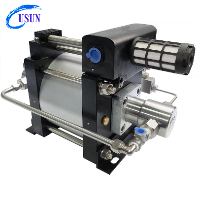
Popular Usun Model :AT -CO2 type 160mm driven
double acting pneumaticdriven Liquid CO2 transfer pump for
tank refilling General Information for Air driven liquid
pumps USUN air driven liquid pumps are
ratio devices that utilize low pressure
compressed air driving a larger diameter piston (area x
pressure) which is linearly connected to a
smaller hydraulic piston/plunger. Using this ratio
principal, a higher hydraulic pressure can be
generated. Usun Pump model numbers reflect the pumps
nominal pressure ratio, while the technical
data indicates exact ratios. The outlet stall
pressure is easy to set by adjusting the air drive
pressure through a simple air pressure
regulator. By multiplying the pressure ratio by the
available shop air pressure, the nominal liquid pressure
can be calculated. Exmple ( Pump Model: AT644 liquid
pump) Air drive piston area ( 160mm Ø) Hydraulic
plunger area ( 20 mm Ø) Actual ratio = 64:1 1.
AIR DRIVE SECTION The air drive section consists of a light
weight piston complete with seals running inside
an aluminum barrel. The diameter of the air piston is
80mm. When compressed air is supplied to the pump the
air pushes the air piston down on a compression stroke (
forces fluid out of the liquid end). Under
the control of pilot pins (poppet valve) triggered at each end
of the stroke 2. HYDRAULIC SECTION (Wetted End) The
hydraulic section of an air driven liquid pump consists of 4 main
pieces, the hydraulic body, the piston/plunger, the check
valves and the main high pressure seal. The
hydraulic piston/plunger is directly linked to the
air piston and it is housed inside the hydraulic body and its
movement up and down creates the liquid flow into and out of
the pump through the check valves. The check valves
are spring loaded and on the suction stroke the inlet check
valve opens to the maximum allowing fluid into the
hydraulic body and on the compression stroke the inlet check
valve closes and the discharge check valve opens forcing the
pumped fluid into the process. The main high pressure seal is
located within the hydraulic body and the piston/plunger
seals against this during operation. There are
different materials and designs of high pressure
seals depending on the fluid being pumped and the maximum
pressures of the pump, however the standard seals
are suitable for both water and hydraulic fluid
use. USUN air driven liquid pumps are self-priming,
However, high ratio pumps are more difficult to Prime and
may require bleeding. In general, it is not recommended to use an
air- line lubricator. USUN air driven liquid pumps cycle
automatically as the outlet pressure increases
the resistance also increases and the cycle rate
decreases until the pump stops automatically when the
output pressure forces are equal. This is referred to as
the stall condition. The pump will restart with a
slight drop in the outlet pressure or an increase in the air
drive pressure. Pump performance can be affected by a
number of conditions, such as freezing of the exhaust
muffler or pilot valves (which is caused by moisture in air
lines), inadequate inlet air-line sizes and dirty
filers. When operating the pumps on a continuous basis, we
recommend you use a maximum cycle rate of 50~60 cycles
per minute. This will both increase service intervals and
assist in preventing ice forming at the exhaust. An air supply
dryer will also assist in reducing icing up. To obtain best
overall performance, it is recommended not to reduce the indicated
port sizes and consult We for flow conditions not shown
in charts.Typical applications for pneumatic driven water
testing pump Key featuresOne model available in 8
ratiosCompatibility with a variety of liquidsSafe pneumatic
operationAluminum bodies and wetted materials of carbon steel or
stainless steelRugged,compact,reliable and easy maintenance proven
designHigh quality seals, long service life availableNo need for
air line lubricationWide application with large range of pressure
ratioMain technical data Typical technical data for pneumatic
driven water pump AT Serial Air liquid
pump Technical
data
Base on air driven at 7Bar , air consumption is around 0.9M3
per min Base on air driven pressure at 7BarModelPiston/Rod
diameter ø(mm)Displacement per stroke (mL)Liquid INLiquid
OUTMaximum outlet pressyre Bar@at 8.3BarLiquid Outlet
pressure (Bar)
1Bar=0.1Mpa=1.019Kg/cm²0204070100150200300400500600700900120017002350Flow
rate
L/min (L/min)AT1050294.52NPT3/4''NPT3/4"8335.3426.5120.6217.6711.78 AT1640188.5NPT3/4"NPT3/4"132.822.6216.9713.211.317.54 AT2035144.32NPT3/4"NPT3/4"16617.3214.4312.9911.5510.10 AT2830106.03NPT1/2"NPT1/2"232.412.7210.69.548.487.426.360 AT402573.63NPT1/2"NPT1/2"3328.847.366.635.895.154.423.680 AT642047.12NPT3/8"NPT3/8"4985.654.714.243.773.32.832.361.881.41 AT801838.17NPT3/8"NPT3/8"6644.583.823.443.052.672.291.911.531.341.15 AT1001630.16NPT3/8"NPT3
Quality Popular Model: At28-C02 100-200 Bar Pneumatic Driven Liquid CO2 Transfer Pump for Tank Refilling products, provide good price Popular Model: At28-C02 100-200 Bar Pneumatic Driven Liquid CO2 Transfer Pump for Tank Refilling from .
Related products about Popular Model: At28-C02 100-200 Bar Pneumatic Driven Liquid CO2 Transfer Pump for Tank Refilling
-
 Waste Tyre Plastic Recycling Machinery Machine Tire Crusher Production Line Rubber Crumb Grinding Machine Equipment Tire Shredder
-
 Stretch Plastic Blowing Pet Bottle Making Blow Molding Machine Bottles Stretch Automatic Pet Bottle Blowing Machine
-
 Waste Plastic Pet Bottle, Water Bottle Flake, PP/HDPE/LDPE PE Film Jumbo Woven Bags Plastic Crusher Machine, Plastic Crushing Washing Recycling Machine
-
 Type 2 Wall-Mounted Electric Car Charging Station 7kw /11 Kwelectric Vehicle Charging Station Home Wallbox AC EV Charger Single Phase or 3three Phase
-
 G-View G12W Wholesale Auto Car LED Headlight Bulb High Power H13 H11 9005 H7 H4 Car LED Headlights LED Car Lights
-
 New Design Porcelain Round Plates Dinner Set for Wedding and Banquet
-
 China 2023 New Design Super Soft 100% Polyester Microfiber Knitted Oversized Decoration Hoodie Blanket
-
 Handmade Art Creative Materials Thickened White Paper Cup DIY Disposable Handmade Colored Paper Cup


