SummaryTransformers immersed in insulating fluid with natural self
cooling (ONAN), three-phase, 50/60 Hz. For indoor or outdoor use.
Hermetically sealed, CRGO Silicon steel, High-strength cold-rolled
steel tank. StandardThe transformers described in this catalogue
are designed and tested in accordance to IEC/BSEN 60076.
FeaturesCommon power ratings: 30, 50, 80,100,125,160, 200, 250,
315, 400, 500, 630, 800, 1000, 1250, 1600, 2000, 2500 kVA. This
transformer is designed for voltages of ≤ 36 kV. Specific figures
are not given for this parameter because of the wide variety of
voltages used. Transformers can be supplied on demand to run
at two different primary voltages, the shift between these input
voltages has twobasic alternatives:• with a primary tap changer
which can be switched with no load and no applied voltage• or by
changing terminals under the cover.The secondary voltage under no
load is allocated at 400V, 415V, 433V, though other
voltages can be supplied on demand. When usage requires two
voltages, transformers with two simultaneous voltages can be
supplied. In this case the no-load voltages are set to
400V(230V),415V(240V),433V(230V) .The connections normally
used are as follows:• For rated power levels of 160 kVA or less:
Yyn0• For rated power levels over 160 kVA: Dyn11.• Dyn5, Yd11 and
others can customaized.As per IEC /BSEN 60076 standards these
areset in accordance with the highest voltage for the
material,being the level immediately above the rated
voltage.Material maximum admissible
voltage12kV17,5kV24kV36kVWithstand
voltage28kV38kV50kV70kVBasic insulation
level75kV95kV125kV170kVAs per IEC/BSEN 60076 , in normal operating
mode: • 60º K max. in oil • 65º K average in windings Other
temperature rise levels on demand. Transformers covered must have
one of the following oil expansion systems: a) an external
conservator tank b) an air chamber under the cover c) a
hermetically sealed elastic tank ROOQ recommends option (c), which
is the one considered in this catalogue, as it has the following
advantages: 1.Smaller size, as there is no need for an conservator
tank or air chamber, making for easier transformer transportation
and placement. 2.Lower overall weight. 3.Increased sturdiness and
less risk of leaks, there being no weak points such as welds
between the expansion tank and the cover, oil level
gauge, Silicagel air breather, etc. 4.Low maintenance due to the
absence of elements such as the drier, over-pressure valves and
liquid level indicators. 5.No degradation of insulating liquid
(oil) by oxidation or absorption of moisture, as there is no
contact with the air. The liquid therefore remains in ideal
condition. 6.Better conservation of seals due to lack of contact
with air, which means that they stay more flexible. Construction
detailsI- MAGNETIC CIRCUITOriented grain, very low loss magnetic
plate is used following IEC/BSEN 60076. The type or class of plate
is chosen on the basis guaranteed noise level and losses. The net
cross section is maintained constant in limbs and yokes throughout
the magnetic circuit, as a special configuration does away with the
need for cross-section reducing grip bolts (section reduction).The
limbs and yokes are joined by 45º lugless joints, with complete
one-piece yoke, and stacking is arranged so that each plate profile
is staggered with regard to the previous one, thus minimising the
effect of the gap. The profile is stepped, with the number of steps
required to obtain the best coefficient of useful surface area.II-
LOW VOLTAGE WINDINGThis winding is located next to and concentric
with the magnetic circuit. Two clearly different types of wire are
used depending on the allocated current:- Rectangular cross-section
with rounded edges. - Strips with conditioned edges.In the
former case each wire is insulated with thermal class A cellulose
paper or class H enamel. Strips are used bare.The rectangular wire
winding is set up in a complete layer configuration with one or
more concentric channels for cooling.The insulation between layers
is always B status resin impregnated.The width of the strip on
strip type winding with conditioned edges covers the whole axial
width of the coil, so that each turn is a layer of winding. As the
strip is wound a layer of type B resin impregnated paper is wound
with it. This polymerises during the drying cycle, giving the
winding the strength to withstand the mechanical stresses entailed
by short circuits as per IEC 60076 standards.III- HIGH VOLTAGE
WINDINGThis is wrapped around the low voltage winding to lie
concentric with it, separated by an insulation structure giving the
level of insulation desired.The conductors used are of two types:•
circular cross-section wire• rectangular cross section strips.The
conductors are insulated with thermal class H enamel. The
rectangular section wires or strips have thermal class A paper or
thermal class H enamel. With both types of wire, the winding
configuration is anti-resonant in one section,
Quality Oil Cooling Type Power Transformer 250kVA with CE Certification products, provide good price Oil Cooling Type Power Transformer 250kVA with CE Certification from .
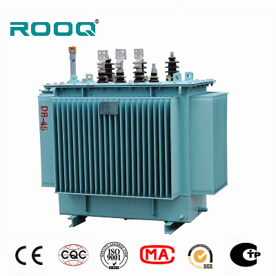
Larger photo of Oil Cooling Type Power Transformer 250kVA with CE Certification
Related products about Oil Cooling Type Power Transformer 250kVA with CE Certification
-
 Waste Tyre Plastic Recycling Machinery Machine Tire Crusher Production Line Rubber Crumb Grinding Machine Equipment Tire Shredder
-
 Stretch Plastic Blowing Pet Bottle Making Blow Molding Machine Bottles Stretch Automatic Pet Bottle Blowing Machine
-
 Waste Plastic Pet Bottle, Water Bottle Flake, PP/HDPE/LDPE PE Film Jumbo Woven Bags Plastic Crusher Machine, Plastic Crushing Washing Recycling Machine
-
 Type 2 Wall-Mounted Electric Car Charging Station 7kw /11 Kwelectric Vehicle Charging Station Home Wallbox AC EV Charger Single Phase or 3three Phase
-
 G-View G12W Wholesale Auto Car LED Headlight Bulb High Power H13 H11 9005 H7 H4 Car LED Headlights LED Car Lights
-
 New Design Porcelain Round Plates Dinner Set for Wedding and Banquet
-
 China 2023 New Design Super Soft 100% Polyester Microfiber Knitted Oversized Decoration Hoodie Blanket
-
 Handmade Art Creative Materials Thickened White Paper Cup DIY Disposable Handmade Colored Paper Cup


